Installation of a Complete Rack and Pinion Front End
INTRODUCTION
The first question always asked is "why?"
I found several reasons to do this project. These reasons may not work for you, but they did justify it in my mind. This 1961 Ford Falcon Sedan Delivery was never intended to be a restored vehicle but rather a real delivery truck for my business. In order to fulfill this role, it had to be reliable and comfortable to drive. When we originally put this vehicle together, a V-8 was a must. The Lincoln Versailles disc brake rear end was the hot setup as well as Granada front discs. These items along with the "Shelby" front suspension modification were incorporated in the vehicle.
I have since learned that it takes a lot more fluid pressure to activate 4 wheel calipers than either all drums or just 2 calipers on the front with drums on the rear. This vehicle never did attain the stopping ability that it should have with 4 wheel discs. This was due entirely to the amount of pedal pressure required to activate all 4 calipers.
Another major consideration was the driving of the vehicle at speed on the interstate. One would think that with the amount of time and money spent to rebuild the front end along with the incorporation of the "Shelby" modification, this vehicle would track straight. This was not the case and the vehicle tended to wander whenever it wanted to. I was able to discover the problem with the front end and could have possibly repaired it, but the trade off wasn't worth it.
I also feel that in order for a Ford small block to develop it's true horsepower potential the exhaust system has to be opened up. One way to accomplish this by installing headers. The headers currently on the market would not fit this application without modification and with custom headers approaching $1,200.00, I felt I could put that money to better use.
Another problem I encountered was the potential for overheating in traffic. I tried every trick that was suggested and it always came back to airflow. I just couldn't get enough airflow in the engine compartment when the vehicle was stopped in traffic. The engine did have 351W heads on it which probably adds 10 - 15 degrees of engine temperature. A 4 row radiator and a 3 1/2" fan shroud just couldn't dissipate the heat at a stop light. Additives seemed to help for a short period of time but lost their effectiveness over time. An electric fan would also help to move the air, but I felt that was treating the symptom and not the cause. This cooling system just needed more airflow and one way to achieve it would be to open up the engine compartment.
After spending several months contemplating this decision, I decide to proceed. The goal is to end up with a vehicle I can steer, an engine that won't overheat in traffic and a 4 wheel disc brake system that will stop the vehicle.
I felt that for me to be able to accomplish this task, a kit was the best way to go. Especially if I could find a complete kit. A person may be able to shop around and buy a piece at a time and save some money, but I was concerned with saving time and not having to shop for every item. The kit used for this project was purchased from Rod and Custom Motorsports. $2,800.00 delivered. I asked for no discounts and none were offered. I wanted to be able to post my conclusions regarding this kit for all to read with no ties to the manufacturer. The kit is complete and no additional parts were required except for different sway bar mounts which the manufacturer promised to ship for free if I could tell him what I needed. I decided to do it myself as I had some material in the shop that would work just fine. Overall rating of the kit is excellent. Overall rating of the instructions is poor as there were none. I hope that these pictures and comments will help anyone contemplating installation of a rack and pinion unit.
The Problem with the Removed Front End
I felt that I should use some space here to demonstrate what was wrong with the old front end and perhaps save someone else the headaches.
Installation of the "Shelby" modification required the repositioning or lowering (approx. 1") of the upper control arms. A steel reinforcement plate is welded in place and an aluminum wedge is installed under the upper ball joints. Theoretically everything will fall back into place and all that would be left is an alignment. This modification has been done for years to the early Mustangs and the 1964 - 65 Falcons. The purpose of the modification is to help eliminate negative camber and the resulting bump steer.
I couldn't find anyone who had tried this modification on this early of a model Falcon (1961). Ford did change the part numbers for the suspension housings in 1964, but no one could tell me what the specific differences were or any reasons why this modification wouldn't work. So of course I had to try it. Looking at these 2 pictures, one can see where the upper control arms were wearing against the inside of the suspension housing. Since this modification works with the later Falcon, one can only assume that the suspension housing is narrower on the early Falcons.
The problem really came to light after installation and during the inspection process before alignment. The tops of both tires were out way beyond the bottom of the tires. Since these Falcons are aligned by shimming the upper control out, it was apparent I had a problem. The solution was to install a lower caster adjusting shim kit in the lower control arms and move them out to catch up with the top. The vehicle was then aligned and all was supposed to be well. I was able to then drive the vehicle and didn't have any appreciable abnormal tire wear. I drove it for about 4 years like this always knowing that it wasn't right but the alignment and tire guys always saying all was well.
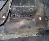
The Left Side
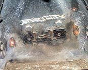
The Right Side
Upon disassembly, it became apparent what was happening. I could have cut the old suspension housings out and installed the later ones or cut the wear areas out of these and driven around with holes in them. There was also the thought of shimming the upper control arms out far enough to stop the rubbing action and then go to the lower control arms and move their pivot points outward. This option would mean that the tire and fender would interfere with each other and I would have to raise the front of the vehicle.
I decided a nice rack and pinion would also solve the problem.
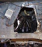
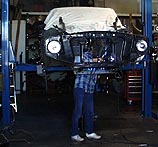
Removing the Shock Towers.
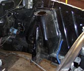
The Left Shock Tower already cut.
The Right Shock Tower already cut.
These pictures illustrate how the shock towers were cut out. Notice the braces to the firewall have already been eliminated. I decided to cut the shock towers as close as possible to make the openings as small as possible. This would make it easier to fit the flat panels and ensure that there would be room left to form a lip on the panel. This in turn would allow the panels to be welded in from both sides to give maximum strength.
The metal lip on the back of both shock towers was actually cut in half. Half of it falling off with the shock tower and half of it remaining spot welded to the backside of the inner fender wells. This metal then had to be removed. I felt it would be better to actually flat grind the metal off rather than drill each spot weld. If I was to drill each spot weld, I would have additional holes to be welded in the engine compartment and since many of the welds were right on the edge of the opening, it would have a jagged edge when trying to fit the new panels. This was a somewhat tedious and time consuming task, but worth the effort in the end.
This is the Left Hand side with the shock tower removed.
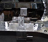
Welding in the Components
The welding process was pretty straightforward and the cross member was designed so that once one side was on center and located, the other side was also. The cross member has a piece of angle iron on the ends. This angle iron is welded to the bottom and the inside of the frame. The coil over shock bracket has angle iron that is welded to the top and outside of the frame rails. This forms a box around the frame rails. The following pictures illustrate the process.
The Right Side with
the coil over bracket
The Left Side with
the Cross member and
coil over bracket installed.
Close up view of
John Elyko's welding skills
This picture is of John Elyko. He is the welder. I told him I would post his picture and make him famous if he would weld the front end for me.
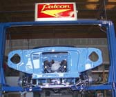
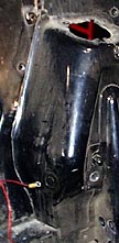
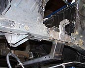
I finally finished the paint and bodywork in the engine compartment. Although I am not a body man, with all of the free advice I received from all who viewed the project, I was able to do a pretty decent job. As you can see, the engine compartment is now blue. It was painted with base coat /clear coat. It has a very smooth finish and should very easy to keep clean.
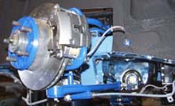
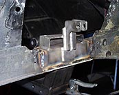
This is a view of the Left Hand Caliper assembly. All of the darker blue parts were powder coated in our shop. We used the Eastwood Company powder coat kit and are extremely happy with the results.
This is a view of the Right Hand caliper assembly. Notice the sway bar mount. This part is the only part that was not adequately supplied in the kit.
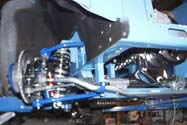
This view of the Left assembly demonstrates the flexible brake line connector. It was decided to use through the frame connectors. This will allow the front brake line from the master cylinder to be run straight down from the master cylinder and then tee'd off to the right side. This will keep the brake lines low in the engine compartment and help maintain an uncluttered look in the engine compartment.
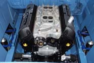
The engine is in!!! As you can see, there is now plenty of room for decent exhaust headers.
12/05/2005 Update.
Well, it has been quite a spell since I wrote any more in regards to the Sedan Delivery. Actually, it has been since June, 2003. One of the main reasons I haven't written more has been lack of time. Time to write as well as time to work on the project. I promised myself that now is the time to finish this one, as I am starting another.
First off, I did finish the project to the point of driving and showing it. I found some problems with what I thought was a completed project and hopefully others can learn from the experiences.
- First problem was the exhaust. No one we could locate makes a DECENT off the shelf header for this application. I tried all that Sanderson had on the shelf for Ford small blocks, but the steering shaft was always in the way. I finally trailered the delivery to them in So. San Francisco. A couple of grand later and I had a nice new brightly shining exhaust system with some beautiful ceramic coated headers.
- The second problem was with the brakes. I thought I had it all worked out using a 1965 Falcon Booster and a late model Mustang master cylinder. First thought was the Power Booster could be made to fit using the 1965 brake pedal assembly and using the Falcon bracket, etc. and the Mustang master cylinder had the correct valves for 4 wheel disc brakes. What I failed to know was that all master cylinders and brake boosters are not created equal. I still had problems stopping and it took way too much pedal pressure. After fooling with this problem for an extended period of time, I discovered that although the booster and master cylinder bolted together and appeared to match perfectly, there was a vacuum leak between the two where you could not see or hear it. A visit with Master Power Brakes, fixed the problem by replacing the booster and master cylinder. Now it stops better, but I not yet completely satisfied with the system and will revisit this area.
- Vibrations. Vibrations. Vibrations. This vehicle had vibrations before installing the front end, but now I had more. The major vibration could be felt on acceleration but was not as noticeable on deceleration. Since this was now a different engine and transmission, those two items were not thought to be the culprit, so it must be the drive shaft itself. The driveshaft had been balanced, so that meant an unbalance condition was not the likely culprit. Now, people were using this Granada Disc Brake Rear End in all types of cars and I couldn't find anyone that had this type of vibration problem. I finally studied the problem in some depth and remembered I had used all of the stock Granada rear end hardware. So, it seemed to me that if folks were buying these rear ends at swap meets etc. and installing them without the original hardware, perhaps something in the hardware could be at fault. When I disassembled the mounting hardware, I found that they used a cast iron metal shim to actually tilt the rear end in the Granada. I was able to remove this shim piece, which straightened out the rear end and that vibration is now gone. It seems there was a bind placed on the driveshaft.
- Engine vibrations. This is one that I suspected when I put the delivery together. In the kit I purchased, they supply 2 metal clad suspension bushings for the engine mounts. I looked at them at the time and thought they wouldn't dampen much vibration, but that is what the manufacturer recommended and it seemed like it was what everyone else was using in their respective kits. I am currently in the process of replacing these mounts with some good old Ford Engine Mounts. This means I will have to destroy the paint in the engine compartment due to cutting and welding, but it will be worth it.
- Steering. The rack & pinion steering is a very worthwhile modification, however, it needs power. I can turn the wheels very easily if moving, have excellent road feel at all speeds, but it is a bear to park and to park into it's stall in the garage is difficult. Power Steering is next on the menu.
So, this is my update. Hope you enjoy it and I promise to finish. I am going back through all of these things because I am also in the process of building a 1963 Ford Falcon Sprint 4 Speed Convertible and I want to make sure I only have to do it once. The Convertible will also use the rack and pinion front end, but it will also have an Air Ride Suspension System.
I am back. Finished up the engine mounts. I ended up using the stock Ford Falcon V-8 engine rubber mounts along with the intermediate mount brackets which were welded onto a short length of 1-1/2 inch right angle steel. I had to bend the intermediate mount brackets a small amount to get a good flush 90 degree fit to the angle iron. What a wonderful thing. All engine induced vibrations are gone and now I can actually see out the rear view mirror when the car is idling.
I also examined the possibility of installing power steering. I purchased a rebuilt rack, pump and lines and was all ready to go. Unfortunately, it won't fit. Since the oil pump is on the front of the Ford small block, there is no way to get rid of the front hump on the oil pan and it interferes with the power rack. Also, the power rack mounting to the frame is different from the manual rack and it just won't fit. If you are going to install a power steering rack, I would install the power rack first. The engine has to sit higher in the body with the power rack vs. the manual rack. I will be investigating the New Ford Modular Engine for my convertible project and hopefully they are different enough that I can install a power rack and still keep the engine sitting low.