Ford Falcon Aluminum Radiator Install


 The Mounting of a Northern Aluminum Radiator in a Ford Falcon.

1.) This Radiator is NOT represented as a direct bolt in for the stock radiator.
2.) This Radiator is an aftermarket product that may require minor modification for a proper fit.
3.) We believe the benefit of additional cooling capability more than offset any modifications required for fit.
4.) This Radiator Core is the same thickness as a stock 3 row which is 2 1/2 inches.
5.) With the Radiator properly mounted, there is a 3 1/2 inch space from the rear face of the radiator to the pulley mounting flange on the water pump. So, for the engine to be in it’s proper location, there must be a space of approximately 6 inches from the core support to the water pump pulley mounting flange.
1961 Ford Falcon Parts

The accompanying pictures and comments are meant to demonstrate how we approach modernizing the Falcon engine along with an effective cooling system. We do not address the installation of 5.0 engines with serpentine belt systems, original fuel injection systems or computer systems since the modifications and parts required are beyond the scope and pocketbook of most do-it-yourselfers. Not to mention the amount of time to answer all of the different questions that would arise. It much easier and cost effective to use the different components ( P/S Systems, A/C Systems with upgraded compressor) found on the original Falcons.

If you are installing a 5.0 engine with serpentine belt system, fuel injection or any other late model 5.0 components we can not be of much assistance as we have not yet installed those components in our Falcons.
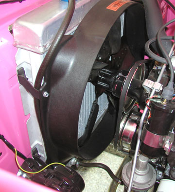
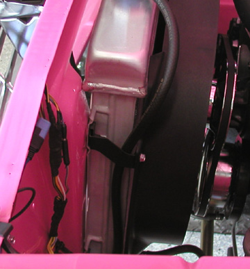
Yes, the top tank is very close to the core support and may even be touching.

A small dimple may be desired for the purist, however it should not be required.

We notice that a 1 1/2 inch spacer is required to get the fan in it’s proper location. Also note that this vehicle utilizes the correct (1965 C-4 ) transmission cooling lines with rubber hose connections to the transmission cooler.

The engine in this particular Falcon is late model 5.0 that utilizes a 50 Oz. counterbalance.

We have changed the original external balanced rotating parts (engine damper and flex plate) to the aftermarket 50 Oz. items to allow the use of the original type V- belts. This also means that we have more than enough room for a fan shroud and a 5 blade fan.

We will also be installing an air conditioning compressor and a power steering pump on this same engine configuration and should not encounter any interference problems.

 Overheating will never be a problem with this set up, it looks reasonably stock and is a clean installation.

Posted in Ford Falcon Technical | Comments Off on Ford Falcon Aluminum Radiator Install

1964-1965 Ford Falcon Dash Pad Install

1964-1965 Falcon & Comet
Dash Pad Installation Instructions

Preparation

   Prior to attempting the installation of your new dash pad the following issues need to be addressed: 

  1. Remove the windshield garnish moldings.
  2. Remove the sun visor moldings and the A pillar moldings.
  3. Remove the lower dash pad trim molding assembly.
  4. Clean any old adhesive and foam that may be left on the steel dash tray surface.

Installation

   Your new dash pad was delivered to you with 10 clips preinstalled in the black side of the pad. They are aligned at the factory and will be very close to the factory slots in your steel dash. We have found that some lateral adjustment may be necessary to fit your particular application. Keep in mind that this pad fits multiple applications. It is recommended that the installer place the pad upon the dashboard area, tipping the pad upward to allow visual inspection of the clips and the slots. At this point adjust the pad left or right as needed and adjust the clips laterally to align with the slots.

  1. Do not trim any material from your new pad yet!
  2. Extra material has purposely been left intact around the ends and lower edges of your pad. It is the installer’s responsibility to ensure that he or she does not remove too much material. We highly recommend that the finished trimming is completed at the end of dash installation only. With pressure being applied to the dash pad in a forward direction, start at the passenger side of the vehicle and engage the tip of the first (right hand) clip. Before pressing the first clip completely into the first slot, align the second clip with the second slot. This method allows you to travel across the dash towards the driver side of the vehicle pressing in one clip at a time until all 10 clips are engaged. Use steady pressure downward on the pad while coaxing the clips into the slots. We have found that a second set of hands does help in fitting the clips into the slots. These clips were probably not one of Henry’s better design ideas and it is difficult to maintain the engagement of all 10 clips. It is our experience that multiple attempts are sometime necessary to get 100% clip engagement.
  3. Once the clips have been engaged it is time to focus on the lower garnish molding. Again with mild forward and downward pressure on the pad use a punch or sharp awl to locate the holes that hold the lower garnish clips in place. Keep in mind that if you distort the pad during this locating process that the finished installation will mirror that distortion. Keep the pad as straight horizontally as possible during the locating process. We found that lying on our backs under the dash allowed us to locate the holes in the metal much easier than from above. Again the help of a second set of hands from above comes in handy.
  4. Once all of the holes are located and punched through the vinyl you may then begin installing the lower garnish molding. We started at the center of the pad and worked out way to the ends one lip at a time. With all the clips installed the pad will be protruding from beneath the molding. Now is the time to carefully trim away the excess pad and foam. Be very careful during this process. The pad must stay clipped under the molding for secure installation.
  5. The A pillar moldings may now be installed and then the sun visor moldings. Again use an exacto type blade to contour the ends of the pad that are exposed between the lower pad molding and the A pillar molding.Congratulations on the Installation of Your New Dash Pad.


Copyright 1997 through 2011 Falcon Enterprises. All Rights Reserved

Posted in Ford Falcon Technical | Comments Off on 1964-1965 Ford Falcon Dash Pad Install

1960-1963 Ford Falcon Dash Pad Install

Installation Instructions for the 1960 – 1963
Ford Falcon Dash Pad

Dash Pad Preparation

   Prior to attempting installation of you new dash pad the following issues need to be addressed:

  1. Remove both the right and left inside A pillar moldings.
  2. Remove both the right & left lower inside trim moldings.
  3. Remove the speaker grille.
  4. Remove both defroster cones.
  5. Remove the radio speaker.
  6. Remove the stainless trim moldings that encompass the lower edge of the dash pad. Use extreme caution when removing these moldings. They are held in place with spring clips and damage to the metal dash and/or the moldings can result if handled improperly.
  7. Remove any old foam or adhesive from the steel dash. This surface needs to be free of all foreign matter to allow for the best fit of the new dash pad. This is a great time to check your skill level. You have been provided with the best fitting product for your Ford Falcon. However, some trimming will be required during the installation process. Your new dash pad was fitted to a stock metal trim fixture prior to shipment to you, as part of the manufacturer’s Quality Assurance Program. Some applications will still require edge trimming and slight foam trimming for the best fitment to your vehicle. If you are uncomfortable with performing these adjustments PLEASE STOP NOW! It will be in your best interests to consult a professional upholstery installer. ONCE THE DASH PAD HAS BEEN TRIMMED OR ALTERED IN ANY WAY, IT IS NON RETURNABLE.

Dash Pad Installation

   Your new dash pad does not need adhesive for installation. The factory trim moldings will sufficiently secure the pad in position. Do not use any contact cement, PERIOD, as it will cause nothing but problems. Ideal installation temperature is 75-80 degrees which will allow the pad to remain flexible during installation. Do not allow the dash pad to sit in extreme heat or direct sunlight for any extended time. The pad will distort and be ruined if subjected to these conditions prior to installation.

  1. Slide the new dash pad onto the metal dash. Check the front edge and curved side edges of the dash pad. They should conform to the metal dash and the front edge where the trim molding will later be installed. Use your hand to check the fitment of the speaker-recessed area of the dash pad to the metal frame underneath. Feeling along the rear edge of the speaker recess you will be able to tell if the dash pad is far enough forward on the metal dash. Gently press the pad forward to allow the pad to slip down into the recessed metal dash. If your dash pad fails to move forward far enough to fit the opening it will be necessary to pull the dash pad away from metal dash and observe the far ends of the dash pad where it contacts the metal dash of the vehicle. Your dash pad may need some foam material removed from the back side of the dash pad where the end horns meet the metal dash. The manufacturer has initially removed some material from this area. However your vehicle may require some further removal of the foam material. Take your time and remove small amounts of foam material in increments checking the fitment often.
  2. Remember, you are only removing foam from the ends of the dash pad that might be contacting the rearward protruding horns of the metal dash. Do not get carried away here. You can destroy your new dash pad if too much material is removed.
  3. Slight trimming of the vinyl skin may be needed on each end of your new dash pad. As the pad fits forward on the metal dash, the front ends will need to be relieved slightly to avoid tearing the dash pad. Temporarily install the stainless steel trim end caps and the A pillar moldings to test fit how much trimming is allowed. Once the pad drops into the radio speaker recess you are ready to begin fine tuning the outside perimeter of the new dash pad. You have been provided with enough material on the dash pad to allow the trim moldings to cover the edges of the pad. USE EXTREME CAUTION! Do not trim away too much material from the edges on your new dash pad. Very little material if any needs to be removed. TAKE YOUR TIME. The final appearance of your new dash pad depends on it.
  4. Use a razor knife to trim away the openings for the defroster cones. Only trim away what you need to install the defroster cones. If you are installing an in-dash radio speaker, you should also trim out that area. Install the speaker grille.
  5. It is now time to install the lower windshield trim moldings. Do not tighten any of the screws until all of them have been started. Then gently tighten all screws evenly. Do not over tighten these trim molding mounting screws as leakage of the windshield rubber seal could occur.
  6. Fit and install the A pillar moldings.
  7. Installation of lower stainless steel trim moldings: Apply a light downward pressure to the dash pad and use an awl to locate the mounting holes for the trim clips. With the clips mounted in the stainless trim moldings begin pressing the moldings in place. Apply pressure only directly over the clip location or the molding will be bent. Continue until all clips are seated. Install the screws in the end caps.
  8. Inspect the installation and when you are satisfied with the fitment, use a razor knife to gently trim away excess material from beneath the lower trim molding. Be careful and do not scratch the paint of the metal dash.
  9. FINISHED.
  10.  


Copyright 1997 through 2011 Falcon Enterprises. All Rights Reserved

Posted in Ford Falcon Technical | Comments Off on 1960-1963 Ford Falcon Dash Pad Install

Priorities

PRIORITIES

BY ERNEST KUCRIEK

I WENT AND BOUGHT NEW PISTONS

THE ENGINE I HAD BORED

I SPENT SO MUCH MORE MONEY

THAN I COULD EVER AFFORD.

I BOUGHT A CAM FOR CHRISTMAS

AND LIFTERS ALL BRAND NEW

NO MONEY LEFT FOR CHILDREN

I ASKED THEM TO MAKE DO.

A STALL CONVERTER FOR VALENTINES DAY

A SHIFT KIT AND SHIFTER TOO

MY WIFE’S A BIT UNSETTLED

BUT, HEY MY CAR’S MY VALENTINE TOO.

I BOUGHT THE BEST SUSPENSION

THE PRICES OVERBOARD

BUT IT WAS EASILY PAID FOR

WITH HOUSE PAYMENTS IGNORED.

THEN I GOT NEW WHEELS

OF COURSE NEW TIRES TOO

AND A NOTE IN THE MAIL

LIFE INSURANCE OVERDUE.

OF COURSE THERE WAS THE BLUEPRINT

AND BALANCED THROUGH AND THROUGH

JUST TO BE ON THE SAFE SIDE

EACH NUT AND BOLT BRAND NEW.

AND NOW I GET HER PAINTED

WITH PEARL AND PALE BLUE

OH, DID I FORGET TO MENTION

MY WIFE HAS LEFT ME TOO.

THEN EVERYTHING REPLATED

I DID THE HEADERS TOO

TIME TO GET A SECOND JOB

CHILD SUPPORT IS DUE.

I GUESS IT ALL SEEMS SILLY NOW

I DID GO OVERBOARD

TRYING TO MAKE MY CHEVY

LOOK AND RUN AS GOOD AS A FORD.

Copyright 1997 through 2011 Falcon Enterprises. All Rights Reserved

Posted in Ford Falcon Technical | Comments Off on Priorities

1960-1965 Ford Falcon Instrument Gauges

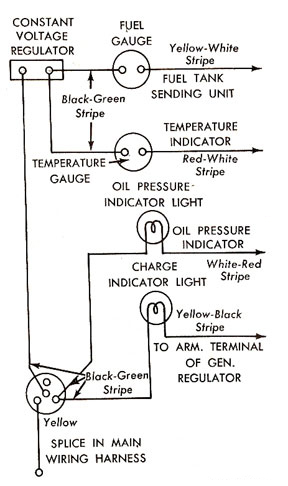
The Fuel and Temperature gauges as used in the 1960 – 1965 Ford Falcon are very basic instruments whose operating principles seem to have gotten lost in this modern day era of digital electronics. In order to properly troubleshoot the circuits you will need an ANALOG voltmeter and 2 “D” cell batteries. It is best you perform all of the troubleshooting techniques before ordering parts for repair as there is a NO RETURN POLICY on any electrical items.

Instrument Panel Gauge CircuitTroubleshooting Fuel and Temperature Gauges

The circuit diagram demonstrates that both the Fuel and Temperature gauge circuits receive their operating voltage from the same Instrument Panel Voltage Regulator. So what affects one circuit will also affect the other circuit. I.E. If one gauge is inaccurate the other gauge may also be inaccurate.

Proper Troubleshooting Techniques
1. Remove the screws that retain the instrument cluster to the dash. Disconnect the speedometer cable from the rear of the instrument cluster and pull the cluster forward. You should be able to access the rear of the cluster and lie it on the steering column. A towel would help prevent the column paint from scratches.

2. Turn the Ignition Key to the “ON” position. Check the voltage on the “Green-Black” wire at one of the gauge connections. The voltage should fluctuate between Zero and Ten Volts. This is the same Voltage that will be seen at the connection of both sending units.

3. If the voltage is incorrect the instrument panel voltage regulator may be defective.

4. Connect 2 “D” cell batteries in series so you will have a 3 volt output. Connect the battery output to the terminals of the Fuel or Temperature gauge. Connect the Positive Battery output to the “Black-Green” terminal and the Negative Battery output to the “Yellow-White” terminal. The gauges should read “Full” or “Hot” respectively. If not, replace the gauge.

5. One item that is often overlooked is the Grounding System. The Engine and Chassis must both be properly grounded for the gauges to work properly. Ensure the Battery Ground Wire is properly connected to the Engine and that the Engine Ground Strap is properly connected to the Firewall. Just because the Engine Temperature Gauge is functioning correctly, you can’t assume the Fuel Gauge Circuit Ground is O.K., because the Fuel Level Circuit gets it’s ground from the Engine – Firewall strap and the Engine Temperature circuit gets it’s ground from the Battery Ground Cable.

6. Now that you have checked and made certain the Gauges and Ground Circuits are correct we can move on to the Sending Units. The Sending Units are nothing more than Variable Resistors. The Temperature Resistance is changed with Engine Heat and the Fuel Resistance is changed with the the level of Fuel in the Tank. If you were to disconnect either wire going to the respective sending units and momentarily touch that wire to the electrical ground with the Ignition Key in the “on” position, the gauge should go to full. If not, there is an open circuit between that sending unit and it’s respective gauge.

7. Most folks want to immediately challenge the accuracy of the sending units when the gauges don’t read where they think they should. Yes, both sending units are immersed in some type of moisture of varying temperatures and conditions and can be problematic. However, the Gauges and the Constant Voltage Regulator are subjected to constantly changing voltages and currents and rely on the difference in the electrical properties of different metals for proper operation. These metals will also deteriorate over time and affect the accuracy of the circuits. So, after you have done all of these checks and the gauge still doesn’t read correctly, the sending unit is probably defective and should be replaced.

8. DO NOT connect any 1960 – 1965 Ford Falcon sending units to a Positive 12 Volts at any time. Your unit will not be repairable as it not designed to operate at that voltage for a sustained period of time.

Copyright 1997 through 2011 Falcon Enterprises. All Rights Reserved

Posted in Ford Falcon Technical | Comments Off on 1960-1965 Ford Falcon Instrument Gauges

Ford Falcon Power Steering Pumps

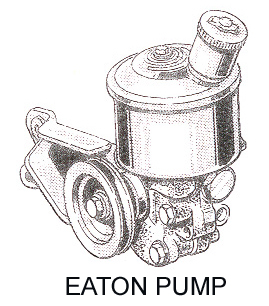
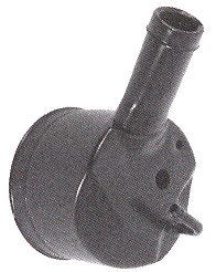
How to Identify your Ford Falcon Power Steering Pump.

Once we know what to look for, it’s easy to identify the difference between the Eaton Style Power Steering Pump and the Ford Style Power Steering Pump.

Posted in Ford Falcon Technical | Comments Off on Ford Falcon Power Steering Pumps

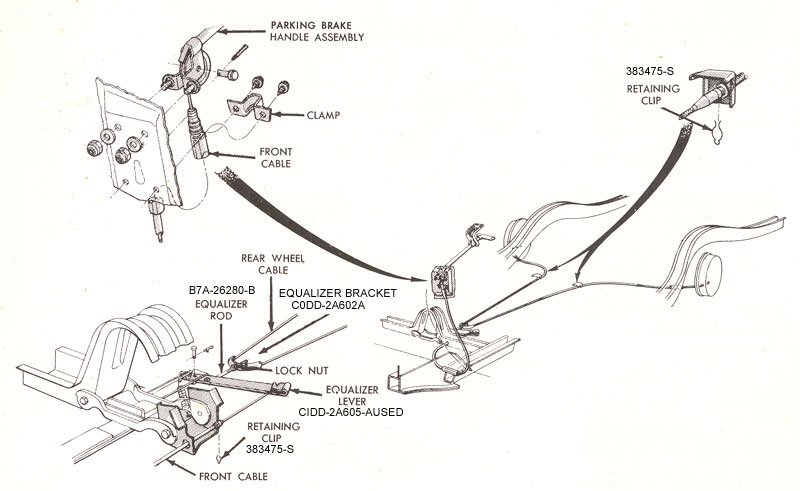
1960-1965 Ford Falcon Parking Brake System

1960-1965 Ford Falcon and Mercury Comet Parking Brake System. Except Convertibles. The Difference with the Convertibles is with the Equalizer Lever and where it attaches to the vehicle.

Posted in Ford Falcon Technical | Comments Off on 1960-1965 Ford Falcon Parking Brake System

Installation Instructions for the F7078 One Wire Voltage Regulator

Installation Instructions for the F7078 One Wire Voltage Regulator

This is a 60 ampere device. It will not work on any alternator that has a higher ampere rating. 
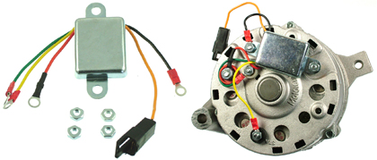
Convert Ford Falcon From Generator to Alternator

  You must furnish a 1965 – 1972 Ford Alternator. We only provide the voltage regulator that mounts on the back of it.

1. Disconnect battery.

2. VERY IMPORTANT: Add a 10/32″ nut on each ground stud on the back of the alternator. These will act as stand offs and prevent the wires from getting pinched against the case and shorting out.

3. Connect the black wire to one of the ground studs while mounting the regulator and secure assembly with 2 more 10/32″ nuts.

4. Connect the red wire to the large red insulated terminal labeled ” bat “.

5. Connect the green wire to the terminal labeled ” fld “.

6. Connect the yellow wire to the terminal labeled ” sta “.

7. Install alternator on the engine.

8. After installing the alternator and one wire voltage regulator, there is only one wire involved to make the alternator charge the battery. One 10 gauge wire from the back of the alternator – BAT terminal to the positive side of the starter relay. That is it. The alternator will now charge.

9. If you want to use the in-dash warning light, it must be connected to the Orange wire on the new regulator.

10. Now the problem is what to do with the wires on the old generator? Since you don’t use the wires, you may remove them or just tape them back. However, if you want to hook up the warning light, you might want to use one of the existing wires to do that.

   We have found that using the white wire from the field terminal of the old generator, which is now disconnected can be connected to the Orange wire of the new regulator. Now all we have to do is find the other end of this white wire and the wire that leads to the warning light, connect those two ends together and the warning light should function. The other end of the white wire is connected to the FIELD terminal of the original voltage regulator. The warning light wire is a small yellow/black wire connected to the ARMATURE terminal of the old voltage regulator. Disconnect both of these wires from the old voltage regulator and splice the ends together. The warning light should now function.

   Now, what about the old voltage regulator and the rest of the wires going to it? The easiest solution is to just leave it in the car as is. However if you want to remove it, please read on. Again, we already know that the rest of the wires coming from the old generator aren’t to be used so they can be removed, taped back or left connected. They can be left connected as there is no current on them.

   There are some other wires on the old regulator that would have to be dealt with if you want to remove the old regulator. The main ones of concern are the 2 wires on the BATTERY terminal. These are large wires and carry +12 Volts to the ignition switch. If the old voltage regulator is to be removed, these 2 wires must be spliced together to get the +12V to the ignition switch. If the old regulator is removed, there may be an issue with the horn relay wire. Since Ford was inconsistent from year to year with the wiring of the horn relay, you will have to examine this connection to determine how to resolve it if there is a problem.

11. If a warning light is not desired, the orange wire may be cut off flush with the case of the regulator if desired.

12. Ensure engine block, alternator and chassis are all grounded properly.

13. Reconnect Battery.

14. When engine is first started, it may be necessary to rev the engine beyond idle to turn the warning light off and initialize the alternator. This is a function of the alternator not the regulator. I.E. The alternator should be replaced as it was not properly overhauled/rebuilt.
Ford Falcon Ranchero AlternatorCopyright 1997 through 2011 Falcon Enterprises. All Rights Reserved
Posted in Ford Falcon Technical | Comments Off on Installation Instructions for the F7078 One Wire Voltage Regulator

1960-1965 Ford Falcon Outside Door Handles

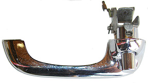
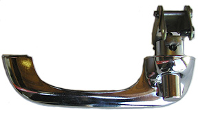
Ford Falcon Door Handle Identification
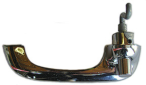
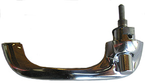
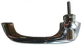
These pictures demonstrate the various door handles used on the U. S. manufactured Falcons from 1960 – 1965. The outward appearance of the handles remained the same throughout the production range. The hardware used to activate the locks was changed several times and is the only real difference between the handles. All of the various hardware is interchangeable between the handles with the only difference being the hole used for the locating tab. To replace the handles on the 1960 – 1962 Falcons the 1964 – 1965 handle could be used by drilling a new hole for the locating tab and reusing the old hardware. On the 1963 Falcons, the 1964 – 1965 handles can be used simply by using the old hardware.

We do not have exact start and stop dates for the production of the door handles and are aware that the manufacturer did, at times, go back and use parts that were thought to be discontinued. For these reasons, it is best if you physically inspect your door handles to determine which ones may be on your particular vehicle.

1960-1961 Ford Falcon Outside Door Handle

1962 Ford Falcon Outside Door Handle

Early 1963 Ford Falcon Outside Door Handle

Late 1963 Ford Falcon Outside Door Handle

1964-1965 Ford Falcon Outside Door Handle

Copyright 1997 through 2011 Falcon Enterprises. All Rights Reserved
Posted in Ford Falcon Technical | Comments Off on 1960-1965 Ford Falcon Outside Door Handles

6 Cylinder to V-8 Steering Conversion

1960-1965 Ford Falcon & Mercury Comet Manual Steering Conversion 6 Cylinder to V-8

There are several different points of view on converting the Falcon/Comet manual steering from the 6 cylinder set up to the V-8. We are presenting our point of view to educate the customer so they can make the decision that is correct for them. The main reason to convert the steering and front end components is to upgrade to V-8 brakes, whether disc or drums. We have found that the majority of our customers want to use the 1974-1979 Granada disc brakes. We are not prepared to go into all of the options and pros and cons of different braking systems at this time, only to get the necessary steering components in place so that you will be able to attach the spindles and brakes of your choice.

1960-1962

The early Falcons have their own set of circumstances that must first be dealt with. The ball joint studs on these early cars are too small to accept the later spindles. We recommend changing both the upper and lower control arms to the 1963-1965 Falcon/Comet control arms. The 1963-1965 Falcons/Comets do not have this problem and the ball joints should only be replaced if they are worn out.

1960-1965

We are aware that Ford did some strange things in the production of these cars and subsequent owners have done some even stranger things. We are going to make an assumption that may or may not be true in all situations. We assume that if you have a 6 cylinder Falcon/Comet produced between 1960-1965, it has a 1″ sector shaft in the steering gear box. You can verify this fact very easily. If a 1-1/8″ socket will fit on the nut that retains the pitman arm to the sector shaft, then you have a 1″ sector shaft. If it takes a larger socket, then you have a 1-1/8″ sector shaft and someone has probably changed the steering box.

The main ingredient to the steering conversion is the center link. The only product that will fit correctly must come from a 1963-1964 or 1965 V-8 Ford Falcon/Comet. The 1963-1964 and the 1965 center link are completely different and cannot be interchanged. We recommend the 1965 V-8 center link for several reasons. The first reason is that the 1965 center link is reproduced and readily available. The second reason is cost, not the cost of a used 1963-1964 manual steering center link versus a the cost of a new 1965 manual steering center link, but rather the cost of the attaching parts. If replacement parts are ever needed, it is much less expensive to use the 1965 parts.

Part Description 1963-1964 Part Number 1963-1964 Price 1965 Part Number 1965 Price
Center Link Part is Not Available Part is Not Available C5DZ-3304-A $150.00
Inner Tie Rod C3DZ-3A130-H $76.95 Each Times 2 C5ZZ-3A131-D $28.00 Each Times 2
Outer Tie Rod C3DZ-3A130-G $76.95 Each Times 2 C5ZZ-3A130-D $28.00 Each Times 2
Idler Arm C3DZ-3352-KR $172.95 C5ZZ-3352-A $47.75
Idler Arm Bracket Included in Above Item Included in Above Price C3DZ-3351-A $33.95
Tie Rod Adjusting Sleeve C2AA-3310-B $9.50 Each Times 2 C2AA-3310-B $9.50 Each Times 2
Pitman Arm Part is Not Available Part is Not Available C5ZZ-3590-A $64.95
Total Price to Convert $499.75 ++++ $442.70 Complete
Note1: You would only use these tie rod ends if you would be using 1965 Falcon/Comet V-8 Spindles. If you are using the Granada or some other disc brake set up, you will have to purchase the correct tie rod ends for those spindles.

Copyright 1997 through 2015 Falcon Enterprises. All Rights Reserved
Posted in Ford Falcon Technical | Comments Off on 6 Cylinder to V-8 Steering Conversion